Universal Controller Reassembly
This procedure covers reassembly of the Universal Controller (UC) on units SC00009 and later.
Before You Begin
This procedure assumes:
The Feed Controller is already installed.
The Engine Control panel is already installed.
The battery cables are connected to the battery terminals.
The Feed Controller cable is connected to the Junction Box.
The following diagram shows an overview of the Universal Controller assembly on the rear AeroCube.

Engine Control Panel to DCAN
Take the cable from the Engine Control panel and pass the cable end through the cable hole.
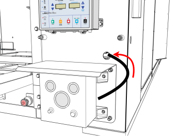
Connect the end of the cable to the top connection on the DCAN. The DCAN enclosure is located underneath the hopper, directly behind the Engine Control panel.

Repeat these steps for the Front AeroCube and the Rear AeroCube.
DCAN to Feed Controller
Take the cable that is connected to the bottom connection on the DCAN.

Pass the cable end through the cable hole and connect it to the Feed Controller.
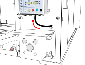
UC to Feed Controller
The UC is located behind the Rear Feed Controller.
The cables that connect the UC to the Feed Controller are already connected at the UC.
Take the end of the cable located behind the Front Feed Controller. Pass the cable end through the cable hole next to the Front Feed Controller and connect it to the Front Feed Controller.
Take the end of the cable located behind the Rear Feed Controller. Pass the cable end through the cable hole next to the Rear Feed Controller and connect it to the Rear Feed Controller.

Antenna to UC
The corner post with the antenna is located to the right of the Rear Feed Controller.
Gently pull the cable ends out from the bottom of the post.
Pass the cable ends through the cable hole.
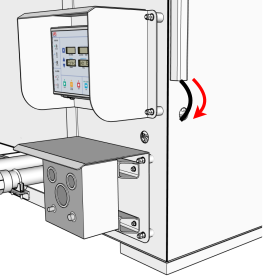
Connect each cable to the UC. Each connector is color coded. From left to right, the connection order is: blue, black, red.

Completed UC Connections
The following image shows all cable connections at the UC once installation is complete.

Verify Power
After connecting all cables, the UC should be powered on. The green circle light on top of the UC enclosure should be lit.

Check the green circle light on top of the UC enclosure.
If the light is not lit, press the Power button once.
The Power button has a circular light around it.
The light turns green when the UC is powered on.