Rotary Motor Power Cable
Components Required

Prepare the Cable
Cut the rotary motor power cable 23 cm from where it enters the existing junction box.

Strip 25 mm of the outer sheath from the cable end. Then strip 5 mm of insulation from each wire.

Install Terminals
Install a terminal onto the red wire.
Ensure the barb on the terminal catches the wire jacket.
Crimp the terminal. Pull the wire gently to confirm it is secure. Check that no conductor strands are outside the terminal — loose strands can cause a short circuit.
Repeat the above steps for the black wire.

Slide the rubber gasket against the connector housing and press firmly until it seats flush.
Insert Terminals into Connector
Pin Number | Wire Color | Description |
|---|---|---|
2 | Red | Positive DC power supply (+12 VDC) |
3 | Black | Ground |
Use a small screwdriver to carefully remove the orange rubber gasket. Do not damage the gasket.
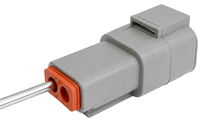
Slide the gasket onto the cables.
Insert the red wire terminal into Pin 2 of the connector until you hear a click. Pull gently to confirm it is locked.
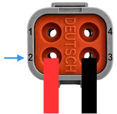
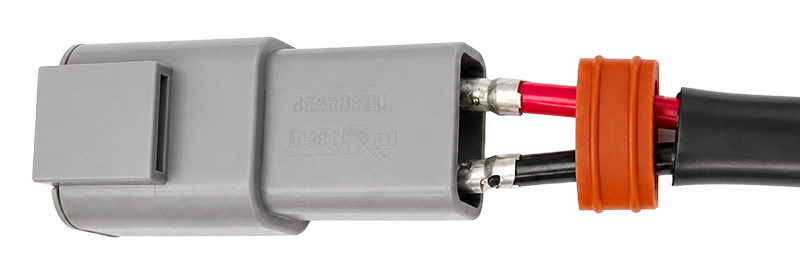
Insert the black wire terminal into Pin 3 of the connector until you hear a click. Pull gently to confirm it is locked.
Install the Wedge Lock
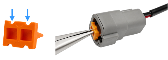
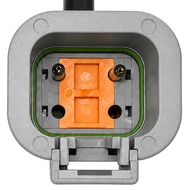
Orient the orange wedge lock so the dip faces toward the pins.
Use needle-nose pliers to insert the wedge lock into the front of the connector.
Push the wedge lock until it is seated flush. If it does not seat cleanly, remove it, adjust the orientation, and try again.
Verification
Confirm continuity between Pin 1 and the red wire.
Confirm continuity between Pin 2 and the black wire.
Confirm there is no short circuit between Pin 1 and Pin 2.
Confirm the wedge lock is fully seated.