Rotary Sensor Cable
Components Required
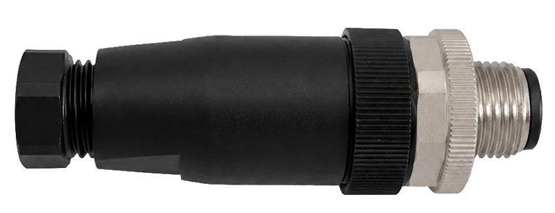
Prepare the Cable
Cut the rotary sensor cable 23 cm from where it enters the existing junction box.

Slide connector pieces 1, 2, and 3 onto the cable. See image below for the correct position of each piece.
Strip 25 mm of the outer sheath from the cable end. Then strip 5 mm of insulation from each wire. Take care not to damage the conductor strands. Keep the exposed conductors clean.

Insert Wires into Connector
Pin Number | Wire Color | Description |
|---|---|---|
1 | Brown | Positive DC power supply (+12 VDC) |
3 | Black | Rotary sensor signal output |
4 | Blue | Ground |
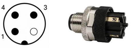
Insert the brown wire into Pin 1. Push fully into position and tighten the screw to secure.
Insert the black wire into Pin 3. Push fully into position and tighten the screw to secure.
Insert the blue wire into Pin 4. Push fully into position and tighten the screw to secure.
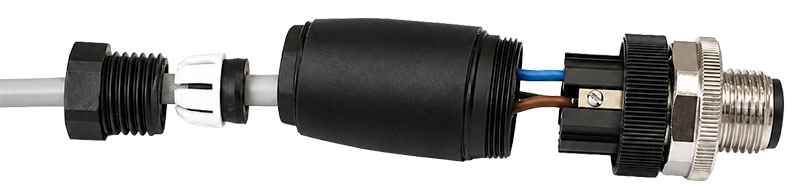
Reassemble the connector: screw the body onto the connector head, slide the gasket into the end of the body, then slide the locking nut onto the body and tighten to secure.
Verification
Confirm all contacts are fully seated.
Pull each wire gently to confirm it is secure. 3 .Confirm the connector body and cable are properly secured.
Confirm the locking mechanism is correctly engaged when connecting to the sensor.