Rotary Sensor - Troubleshooting
When Troubleshooting is Required
A flashing BIN B green light indicates the rotary sensor did not detect a signal within 8 seconds.
See Alarms and Indicators for a description of the BIN B indicator.

Press STOP, then Press START
Press STOP to clear the flashing light.
Press START and observe the feed rate and the BIN B light.
Determine Next Action
Feed rate displays 00
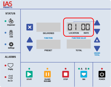
If the BIN B light flashes again and the feed rate displays 00, check that the feed rate knob is not at the minimum setting. A knob at the minimum setting means:
The rotary valve is not turning, or it is turning too slow.
The sensor will not detect a signal.
Adjust the feed rate knob to the a higher setting.
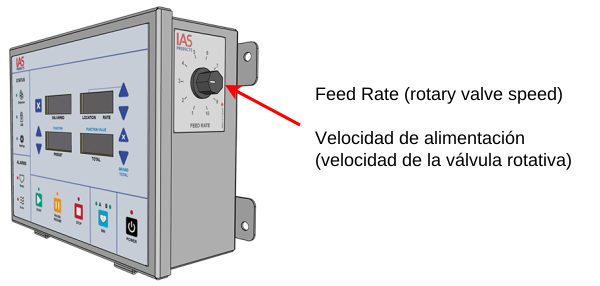
If the feed rate knob is not at the minimum setting and the feed rate still displays 00, troubleshooting is required. Continue to the next section.
Feed rate is not 00
If the BIN B light flashes again but the feed rate is not 00:
The rotary valve is turning and feed is being dispensed.
The operator can continue feeding.
Monitor the feed rate to verify that feed dispensing continues normally.
Tools Required
13 mm wrench
Pliers
Access the Rotary Sensor
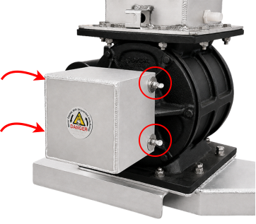
Loosen the four thumbscrews and remove the cover.
If the thumbscrews are tight, use pliers to loosen them.
Check Sensor Operation
The orange sensor light is one of several lights located around the body of the rotary sensor.
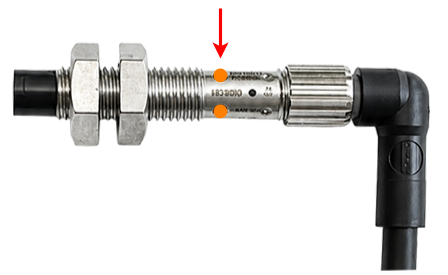
Verify that the sensor light flashes as the rotary valve turns.
For each step that follows, press START and STOP on the Feed Controller to turn the rotary valve on and off. Verify that the sensor light flashes as the rotary valve turns.
If the sensor light does not flash, continue to the next step.
Check the Cable Connection
Check that the locking collar at the cable connection is fully tightened. If it is loose, turn the collar clockwise until it is firm.
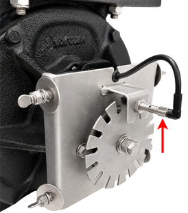
If the locking collar is secure continue to the next section.
Check That the Sensor Plate Is Securely Mounted
Hold the sensor plate and apply light pressure to check whether it moves. If the sensor plate moves, tighten the mounting hardware firmly. Do not overtighten.
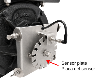
If the sensor plate is secure continue to the next section.
Check Sensor Distance
The sensor face must be ~2 mm from the sensor plate.
Verify that the gap between the sensor face and the sensor plate is approximately 2 mm. If the gap is incorrect, adjust the sensor position and tighten the nuts to secure it.
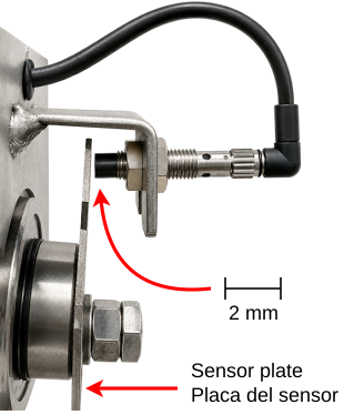
If the sensor distance is correct continue to the next section.
Check That the Sensor Is Firmly Attached to the Bracket
Hold the sensor and apply light pressure to check whether it moves.
If the sensor moves, use a 13 mm wrench to tighten both nuts firmly against each side of the bracket. Verify the distance from the sensor face to the sensor plate is 2 mm.
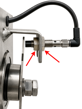
If the sensor is secure continue to the next section.
Remove Sensor to Test
Loosen the outer nut using a 13 mm wrench.

Remove the sensor from the bracket.
Place the sensor face against a metal object. Verify that the sensor light turns on.
If the sensor light turns on, the sensor is working correctly. he problem may be elsewhere. Contact IAS Products for assistance.
If the sensor light does not turn on, the sensor must be replaced. See Rotary Sensor Replacement.